|
|
Post by Trip Rodriguez on Aug 9, 2016 23:26:03 GMT
Here is the info on my dimensions, looking for advice before I drill mounting holes.  Attachments:
|
|
|
|
Post by paulg100 on Aug 10, 2016 5:48:25 GMT
I changed the spacing of the top platform mounting holes to 75mm centre to centre and scaled the rest of the dimensions accordingly. If you change the lever length then in theory that will change the motor mounting positions and the length of the arms.
personally id just use levers with a 160mm hole. You can change how much rotation you use in the software.
If the rest of the dimensions for the top and bottom frame are close to fabis original dimensions then id keep the arms the same, just scale relatively to how much you reduce the c to c of the upper mounts.
I think if you are going to deviate significantly from the original dimensions then you really need to lay things out in cad or you may find your self working things out in hardware which is going to be allot of effort and expense.
|
|
|
|
Post by Trip Rodriguez on Aug 10, 2016 6:23:59 GMT
What about the tie rod lengths? Can you give me the info on the proper relationship between different dimensions?
If I don't need/want the higher angles and displacements I should be able to get more speed out of shorter torque arm settings shouldn't I?
If I go to 130mm on the torque arms what should the other dimensions be? How about at 100mm. If you can give me a link to info where I can calculate it myself that is fine, but I'd like to at least see the numbers before I build.
Thanks!
|
|
|
|
Post by Trip Rodriguez on Aug 10, 2016 9:29:18 GMT
Michael, Based on your comments and similar comments from others I'm considering building my motion sim with shorter travel (shorter torque arms and changing other dimensions to match) so I can get more speed out of it (sacrificing max travel should mean more torque available for accelerations/decelerations over the travel I do have).
Do you use less than full travel for everything, or do you still use full travel for some things like surge and heave for example?
|
|
|
|
Post by paulg100 on Aug 10, 2016 10:36:09 GMT
|
|
|
|
Post by Trip Rodriguez on Aug 10, 2016 13:39:21 GMT
An equilateral triangle? Damn even I can handle that! Thanks Paulg100 for your patience and all the help.
What about the relationship in terms of the (for lack of a better term) diameter of the rod attach points on the upper platform to the diameter of the attach points on the lower platform (crank arms)? I could try to reverse engineer this from GA-Dawg's drawings but I'd be guessing when it comes to scaling it down whether to reduce both by the same percentage or if the relationship between them is something else.
I did spend nearly two hours by the way trying to figure this out online myself, all I did was stare at a bunch of walls of text full of terms I don't know and lots of mathematical formulas that made my head spin =/.
|
|
|
|
Post by GA-Dawg on Aug 10, 2016 14:13:52 GMT
What type of rod end are you using. The angles of movement are actually limited to the rod ends.
|
|
|
|
Post by Trip Rodriguez on Aug 11, 2016 5:44:18 GMT
@ga-dawn I have real race car tie rods (standard stainless heim) stainless currently and have the high angle adapters (5/8" to 1/2") on the way.
|
|
|
|
Post by Trip Rodriguez on Aug 12, 2016 4:43:10 GMT
Ok, on the phone in a campground and still making progress!
So far I've learned the following:
The actuator rods should form two sides of an equilateral triangle.
A line drawn from the gearbox shaft perpendicular to the length of the torque arm should point at that actuator's attachment point to the upper platform when torque arm is in home position.
Actuator rods should be perpendicular to the ground when viewed from the "side", no angle.
|
|
|
|
Post by Trip Rodriguez on Aug 12, 2016 5:55:51 GMT
My plan so far:
Make longer actuator rods so I can maintain the equilateral triangle without scaling down other dimensions (using Fabi's dimensions).
Probably use 30mm shorter torque arms to gain some torque/speed at the cost of some travel because my platform is intended to be used exclusively with VR. I will move the gearboxes in each pair 60mm farther apart to maintain equilateral geometry.
Questions:
Shorter torque arms (smaller radius) mean the load more rapidly moves father from the optimal (for torque) 90 degree angle. How much would this offset my torque gain?
(Still thinking through the following)
If instead of using shorter torque arms I slightly scale my platform up the only losses are shorter travel and the additional weight of the larger upper platform (which should be inconsequential). I still gain torque at the cost of travel and off center weight has less leverage against the machine. Only question I think is whether or not i can enlarge it enough to make much difference. I can probably increase the total machine diameter by 4 or 5 inches and right now i have no idea how much difference this will make. With pass and paper (and light) I should be able to calculate the difference in max angle which will give me some idea.
|
|
|
|
Post by GA-Dawg on Aug 12, 2016 11:46:01 GMT
Hi Trip, I was thinking of how you could layout your setup and here is what I would suggest. Keep in mind that the side space (450mm in you drawing) is not something that is measured but some that is a byproduct of the layout. 1. Lay out a set of gearboxes (1+2 or 3+4 or 5+6) with the 910 mm spacing. 2. Mount the levers to the gearboxes. Make sure you have good clearance with the motors 3. Mount the Rods to the levers and lay them parallel to the gearboxes. 4. Lay the upper platform parallel to the rods and centered between the gearboxes. Here is an image. The blue items need to be parallel. The red item will be based on the part you are using (lever thickness, joint offsets, lever spacer...Etc). The yellow is the mid points that need lineup. 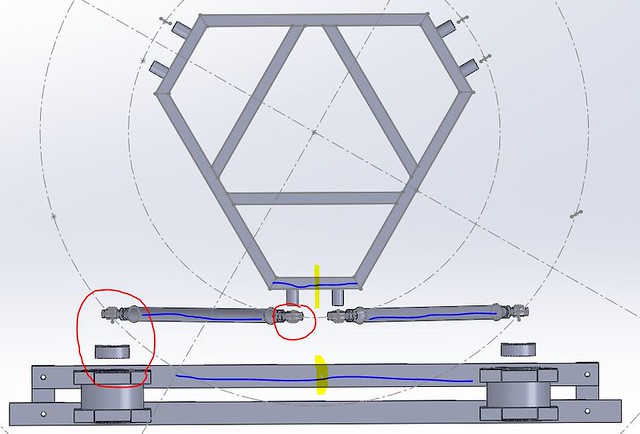 Hope this makes sense and hope it helps. One thing to note if you plan on using BFF or X-Sim you really need to keep track of those measurements as the will be needed. |
|
|
|
Post by Trip Rodriguez on Aug 13, 2016 0:44:54 GMT
Thanks @ga-DAWG I think I've got things pretty well figured out thanks to all the help, good info on this forum, and some internet research. I now think I have a pretty good grasp on the geometry and the reasons for the various relationships.
I will post back here soon with my plan to run it by you folks. I have to do a bit more math and a little thinking.
|
|
|
|
Post by Trip Rodriguez on Aug 13, 2016 3:22:07 GMT
I need a mathematician! I spent the last hour trying but it's just been too long. I have more or less convinced myself (without coming up with real numbers specific to our dimensions) that the loss of torque from the angle of application of force seriously deviating from perpendicular to the torque arm will pretty quickly negate additional torque gained from going to a shorter torque arm.
My guess is that somewhere along the line someone (DoctorD? I sure wish I could get in touch with him.) came up with the ~160mm torque arm as a sweet spot for our applications on average. All I'm trying to do is tweak the dimensions a bit to get a little more speed (by sacrificing max angle/travel) but without spending many, many hours trying to figure out the math I can't figure it out on my own.
Anyone got a way to get a hold of DoctorD besides PM's on X-sim.de ? It's been a couple months since his last log-on there.
I'll also copy this from my new thread over at X-sim.de (That's where I started and how I found out about Thanos so it's only proper I do a build thread there as well). Mostly the content I post there will mirror what is posted here.
-----------------------------------
Looking for advice from an engineer/mathematician:
I've been told by numerous people with similar builds that they are using much less than max travel (via software side adjustments) for VR because speed is extremely critical and angle less critical.
Given that I'm building this exclusively for use with my Oculus Rift I wish to alter the specifications a bit to cater to this special requirement. The problem is I'm not sure what dimensions I should change.
My torque arms have four settings, so I can go to a shorter setting (130mm for instance vs. 160mm) and if that is to be my default setting I will adjust the gearbox mount points a bit to compensate but I did some reading and it seems that the torque lost as the torque arm rotates away from perpendicular to the direction of thrust (moment of the arm) is possibly going to cost me more torque than it will give me. I'd have more torque at the center of travel on each actuator, but the torque would ramp off more steeply as the arm turns farther from center.
This has me even thinking maybe I should lengthen the arm to the longest setting (190mm), but that does mean less torque available from the lever at the center of travel. Adjusting the torque arm settings is no problem, but I want to space the gearboxes for the arm length I think I'm most likely to use and I really don't want to have to move them after the fact if I can avoid it.
The other thing I'm considering doing is actually scaling up the entire rig. This effectively shortens the travel and should gain more torque but leads back to the moment of the arm problem. If the travel is shortened I'm more likely to get into the part of the travel where the angle of the arm causes serious loss of torque.
My favorite solution (but one I'm not sure is advisable) is to scale up the whole machine 18.75% (because that gives me about a 42 inch primary dimension which I figure is good luck!) and use the 190mm torque arm setting. This partially compensates (but nowhere near entirely) for the loss of torque from going to longer arms by shortening travel via a broader spread of connection points, makes up for the reduced torque even more due to the fact that the weight of the platform will be more toward the center of a larger upper frame since the actual sim cockpit won't grow at all with the rest, and smooths out the moment of the arm issue further with a significantly longer torque arm.
The down side is mostly just that it will take up a bit more space, but at least at my current residence I have room (I built a finished room "man cave" in the basement!). I'm hoping a contact I have will be willing to weld up an aluminum upper frame for me so the weight of the upper frame shouldn't increase much at all if I scale up the rig.
Thanks for any help!
|
|
|
|
Post by paulg100 on Aug 13, 2016 7:07:53 GMT
"All I'm trying to do is tweak the dimensions a bit to get a little more speed"
What speed do you want to reach?
what about increasing the frequency of the motor, say 80 or 100hz, that will increase the rotation speed. that is something I plan to experiment whith once I have my pot jitter issues solved.
the limiting factor is going to be the motor/gearbox combination you have, increasing the whole platform size for a longer leaver is not going to give you more torque. the VFD's are still
going to error if they cant reach the acl speed.
DR D is using bigger motors and gearboxes for the longer levers.
already GA is struggling to get his acl lower with 0.75kw and 075 gearboxes on 160cc lever.
|
|
|
|
Post by Trip Rodriguez on Aug 15, 2016 11:23:32 GMT
As far as what I want to reach, really just whatever is best for Oculus Rift VR.
Here is a quick question:
I see most people set their torque arms to be down 30 degrees from horizontal which puts the position where the torque is perpendicular to the arm right at mid travel. This means as you move in either direction up or down the torque slopes off symmetrically. This seems logical, but with these setups (worm drive gearbox) don't we still need less torque for going down, since we aren't lifting all that weight? This being the case, wouldn't we get better performance by having mid stroke be higher than middle of the torque curve?
Again as usual I need to scribble a little bit and make sure that this still makes sense =P. I'll be checking back in =D.
|
|


