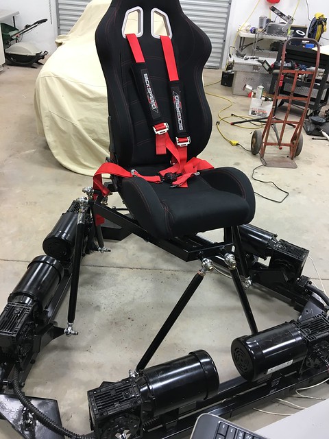
(Just starting this part of the build and will update as I get things worked out...I plan on testing/utilizing with BFF, X-SIM and xsimulator.....
Under Development...zip has not been posted yet....Last update June 16 2016 )
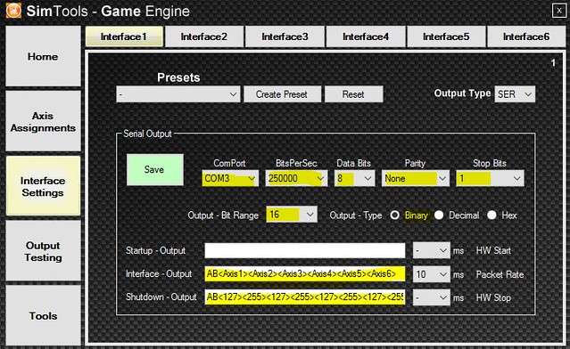
Motion Software Setup
(Side Note: I am using a Windows 10 64bit build to control the simulator)
USE EXTREME CAUTION WITH THE CONFIGURATION FILES IN THE ZIP. THEY ARE SET TO THE DIMENSION OF THE MACHINE IN THIS THREAD AND USING THEM ON OTHERS COULD RESULT IN CATASTROPHIC FAILURE.The software list below goes from simple to advanced. They all have there merit and different levels of support.
1. SimTools (xsimulator.net)
SimTools by Xsimulaor has lots of game support but is lack in the math department so don't expect to much accuracy.
1. Open SimTools and click on Interface
2. Change the ComPort to match the AMC1280USB
3. Copy and past this to the "Interface-Output" ..... AB<Axis1><Axis2><Axis3><Axis4><Axis5><Axis6>
4. Copy and past this to the "Shutdown-Output" ....AB<127><255><127><255><127><255><127><255><127><255><127><255>
....Not sure when I will complete the write on this....
2. BFF Simulation Software (bffsimulation.com)BFF looks simple but is a very powerful nicely written application. It does require you to know a number of dimension and because this was constructed in CAD is fairly simple to do.
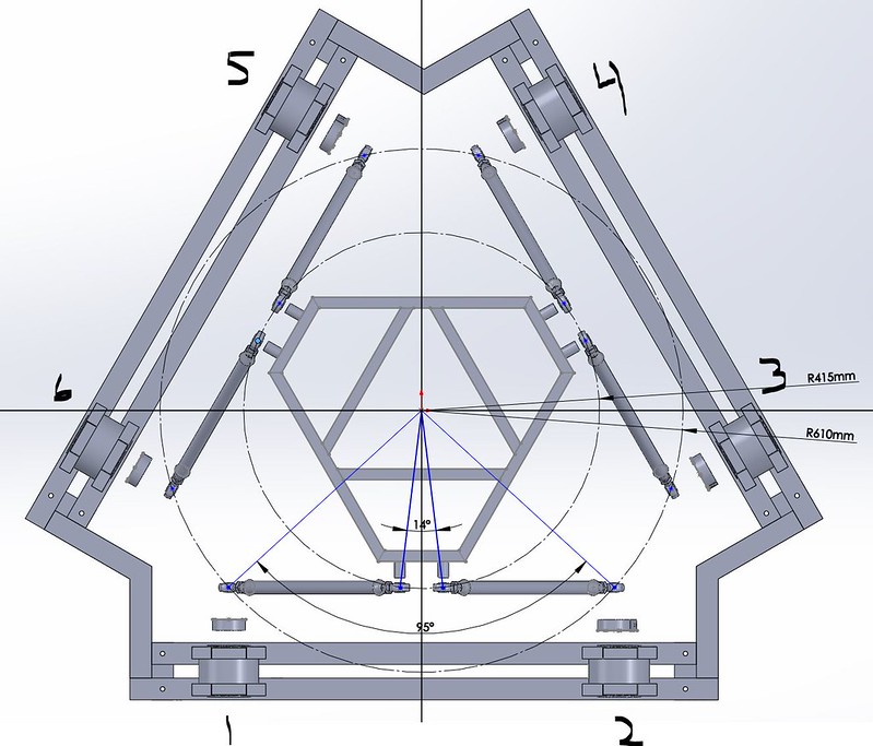
1. First we need the Rad_u and the Rad_b
To do this you need to construct a circle that intersects the mid points of the ball joints. NOTE: With this type of design you need to have the levers in a
vertical position even though that is not a normal condition. You will also notice that I took into account and spacers and offsets.
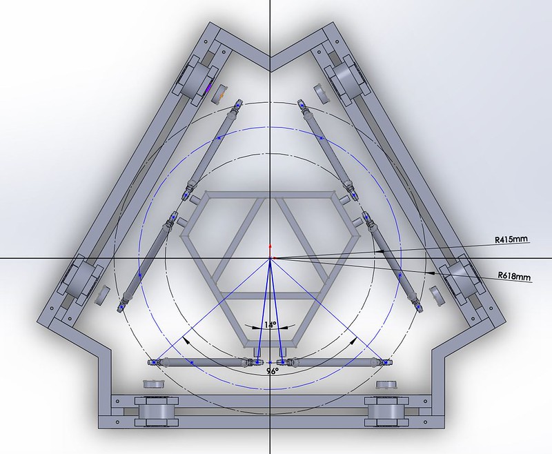
So from the above we know that
Rad_u=415.0
and
Rad_b=618.0
Now we need the H_mid height. To get that we need to determine the midpoint of the lift. Which is a angle of 90 degree between the rod and lever.
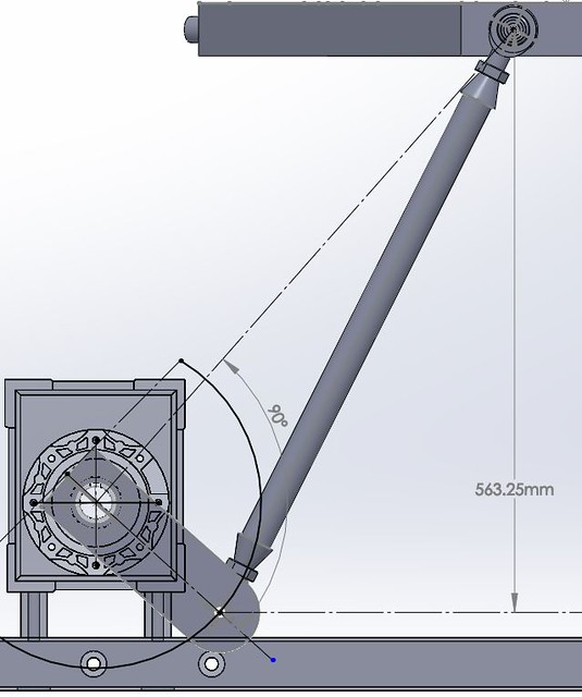
So H_mid=563.3
Next is the Ang_Sub
Leaving the levers the H_mid positions we go back to the top view as this angle should be taken from mid stroke.
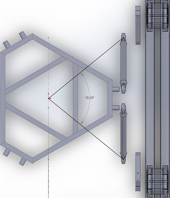
Ang_Sub=78
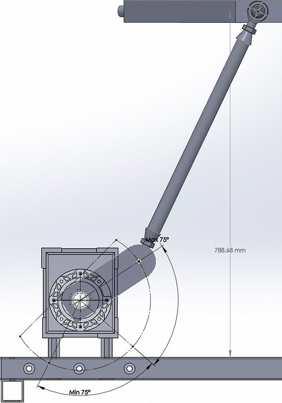
To calculate the Act_Stroke we need to know the lifting range and this is calculated as a 75 degree angle from the starting positions.
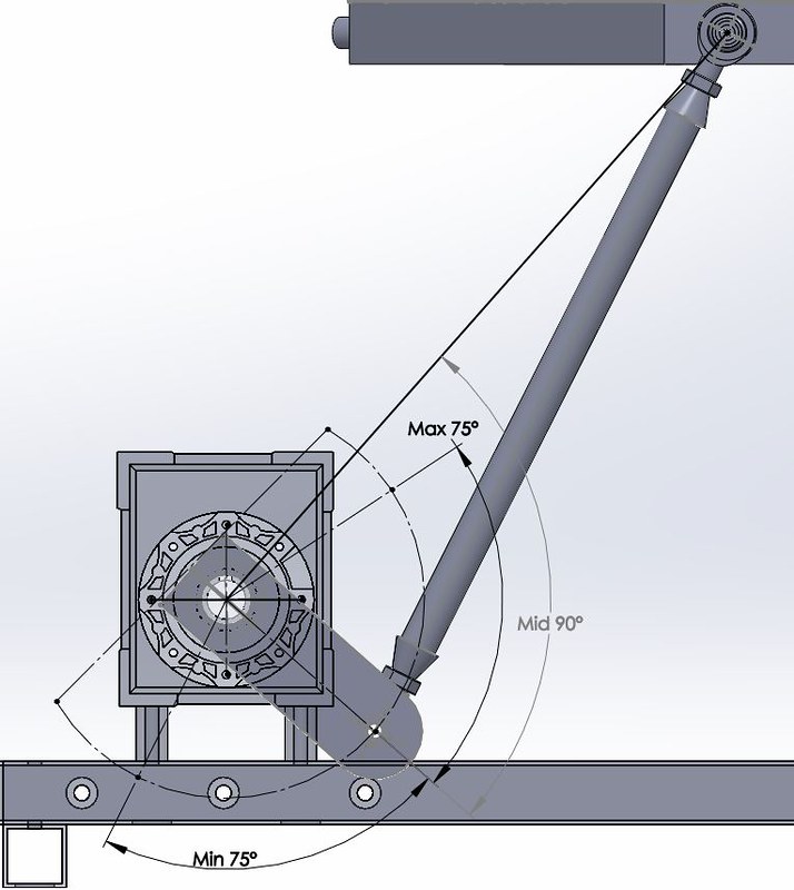
Max Lift
Min Lift
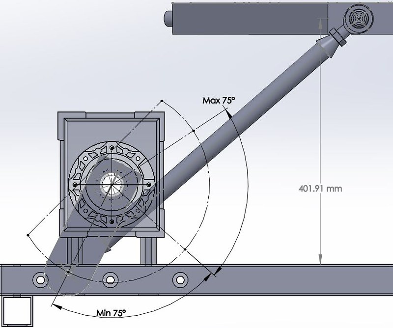
So the total lift or Act_Stroke=788.68 - 401.91 = 386.7
Finally the Crank are radius which is 160mm so Crank_Radius=160mm
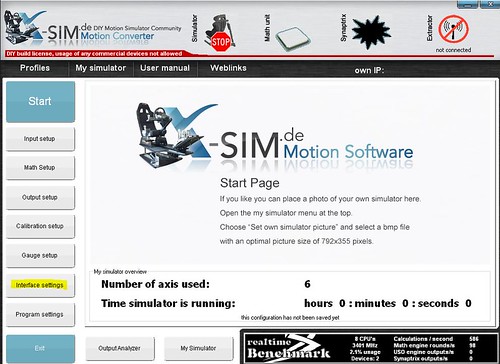
3. X-Sim (x-sim.de)You will need to
register and then
download the x-sim software. This software has the most functionality and is relatively easy to test with.
*******************************************
NOTE: At the time of this writing the default plugin for the AMC (Thanos 6DOF) was a little more challenging and and I am using the one developed by hexpod. Which is located in this
thread. I assume it will go main stream at some point and I will remove this reference.
*******************************************
Once installed you will need to configure the software with your machine dimensions and if you have built one per the blueprints you can just copy and past the 6DOFsetup.ini file that is attached. Assuming you did a default installation the file is located in C:\Program Files (x86)\X-sim\Interfaceplugins\6DOFsetup.ini
If your want to understand what's in the file we need to start with the
[Coordinates]
This part of the file, layouts the physical dimensions of the machine and is the mid point of the attachment points (ball joints). The application is expecting
Y to be Horizontal and
X to be Vertical. The files in the zip are from SolidWorks and have the default orientation meaning
Y is Vertical and
X is Horizontal so the depending on how you have layout your CAD file your X and Y axis my be reversed as in the example below.
![]()
Note: The measurements needs to be taken with the lever arms in a
vertical position with a design like this as the point needs to intersect the drive shaft.
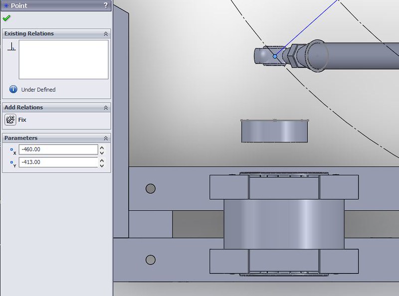
[Coordinates]
Base_1X=-46.000000
Base_1Y=-41.300000
Base_1Z=-150.000000
The image above is from SolidWorks and the scale was mm. The coordinates need to be converted to cm in the .ini file. At this time the Z axis is not used so the -150 is not really important.
Now that you have the coordinates set it is time to test.
Launch X-Sim Converter and click interface settings
than click Thanos6DOF
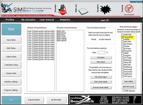
click Disconnect X-SIM
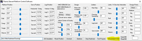
click on the heave slider on the indicator
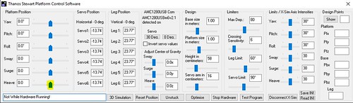
Using the arrow keys (do not use the mouse as a safety precaution) and SLOWLY raise the platform one keystroke at a time. If everything is set correctly you should be able to raise the platform and the limit should stop it before it goes past the physical max height which would be the lever and rod parallel.