|
|
Post by GA-Dawg on May 26, 2016 22:01:14 GMT
1) The first time I put in the values I follow your diagram. The result was to make the physical motor pair 3 and 4 become "front" so none of the movements matched the computer. So I trailed and error until I got it to match (screen to physical motors).
2) When I added the values the servo/motors where point in all different direction. I not sure where the servo number comes from so the best I could do is change the values until I could get something that look right.
Kind Regards,
GA Dawg
|
|
|
|
Post by hexpod on May 26, 2016 22:12:35 GMT
x-vertical
y-horizontal
|
|
|
|
Post by GA-Dawg on May 26, 2016 22:18:56 GMT
When I first did it this was one. 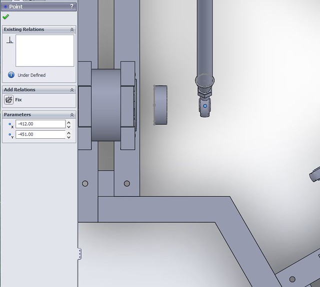 and this was two 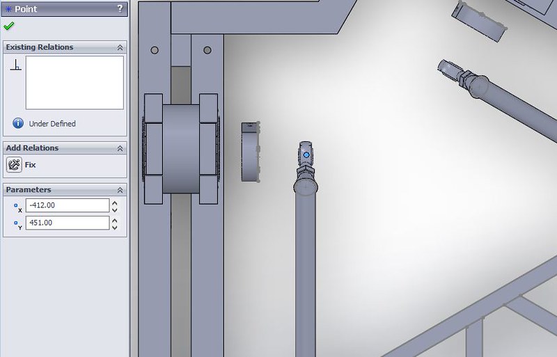 having it this why made surge forward move towards physical motor 3 and 4. |
|
|
|
Post by hexpod on May 26, 2016 22:42:49 GMT
"having it this why made surge forward move towards physical motor 3 and 4."
where? in the 3d representation ?? I think this is fine, your geometry is symmetric so it doesn't matter.
Also if your cad has x horizontal, you have to swap x/y values in the .ini file. |
|
|
|
Post by hexpod on May 27, 2016 10:11:04 GMT
It should look like this: 
the placement of the cubes is not correct but it doesn't matter. the lever orientation is important for math calculations
Could you share the length of your lever and leg please?
cheers |
|
|
|
Post by hexpod on May 27, 2016 11:49:12 GMT
heXpod MOD V3
Please take all safety precautions while testing on a full scale model!
This 6-dof software is working with TronicGR amc1280usb board with or without the 6-dof extension board.
The purpose of this release is to give to the user a geometrically precise 6-dof driving solution as well as a customizable and comprehensible design solution.
www.dropbox.com/s/0d3444kjo5et0gr/6dof%20heXpod%20MOD%20V3.zip?dl=0
You can use it for free, however if you like it, consider PAYPAL donations to imie(at)free.fr
INSTALATION:
- Replace the 6DOF.dll file in the X-Sim/Interfaceplugin folder
- Delete the old 6DOFsetup.ini file
- You can use the .exe offline version for design conception and testing purposes with a similar behavior as the .dll plugin file
FEATURES:
- Understandable size values
- Possibility of saving and reading the optimized heave/surge offset
- 0 deg. servo orientation option
- Custom crank levers orientation by editing the .ini file (values in radians)
- Custom servo and upper joints spacing by editing the .ini file
Instructions for customized spacing for “full scale” platforms:
- Open a CAD project in millimeters.
- Draw the platform and base circles according to your real dimensions and apply your “attach points” with true spacing on those circles. (Fix the center of the circle coordinates at x0/y0)
- Simply divide the platform and base coordinate’s values by factor x10 and copy them to the .ini file.
(Pay attention, swap x values with y values when applying them to the .ini file)
- Open the plugin GUI and press Read INI and Save INI
- In the GUI, set your base/platform size values at 1.00
For the small scale platforms, (up to 20cm), use the same procedure without applying the coordinate’s division factor. Your lever arm length, leg length, platform height, center of gravity and heave/surge offsets will be in millimeter

NOTICE:
- In a full scale platform configuration, all values without ° (degree sign) should be considered as centimeters except the platform/base size, which should be considered in meters
- Platform/base size is a diameter of the circle, while drawing through all the 6 joints
- In the .exe version, after modifying the base/platform coordinates and after loading them from the .ini file, you have to click on the "platform/base size" sliders to update the changes in the 3d representation.
- In every design, you always have to take the "center of the servo" as the base attach points. To fit the 3d model properly, the easy way to find out your base size, is to draw a circle through your lower joints, when the crank levers are fully vertical
- When modifying the size of the platform/base the spacing is modified proportionally (When the base size is set to 1.0, the default spacing between all 6 "centers of the servos" is 50cm.
When the platform size is set to 1.0, the default spacing between the upper joints is 10cm)
- To easily find out your platform’s height, you can measure your leg length from joint to joint, then press the "show" button in the GUI and move the "platform height" cursor until the "leg length" value fits your measurement
- After every geometrical modification, click the "optimize" button to get the corrected motion range
- If you use the “Instructions for custom spacing” procedure, the platform/base size should be set to 1.00 and has to be considered as a size ratio.
- If needed, you can correct the pitch symmetry by applying a surge offset in the "center of gravity" column
- Pay attention - In designs with "arms inside" the "crossing sensitivity" limiter is not applied properly.
Also, the "servo limit" and "optimize" feature are not functioning. you will have to apply a negative heave manually.
CHANGELOG:
- Scaling to meters/centimeters "heXpod MOD"
- Added buttons for swapping the servo orientation 0deg/30deg
- Perspective reduced to minimum
- You can rotate the model with keyboard arrows keys
- Surge/sway sliders corrected
- Corrected slider range
- Top of the cube colors corrected (red motor 1, orange motor 2)
- You can modify and save/write surge and heave offset to/from the .ini file
- Additional custom servo orientation values can be saved/read in/from the .ini file (values in radians)
- Custom "servo center"/"upper joints" coordinate’s values can be saved/read in/from the .ini file
Made by heXpod 19 may 2016
|
|
|
|
Post by vicpopo on May 27, 2016 14:34:45 GMT
Hi heXpod !!
A big thanks to you for your awesome work !
Cheers
|
|
|
|
Post by hexpod on May 27, 2016 15:12:50 GMT
It has to be verified, but from what I understand, there is NO resolution difference between 180 and 360 deg sensors.
It seems that 12 bit sensors can provide:
2048 steps for 180deg model and
4096 steps for 360deg model
@tronic, could you confirm please?
By applying the heave offset for geometry correction, in some cases the arm will have to go a bit over the vertical position.
The best choice in this case will be the choice of 360deg. sensors, especially if there is NO resolution loss.
|
|
|
|
Post by vicpopo on May 27, 2016 16:03:15 GMT
When you look at the datasheet for the resolution :
0,088 ° for the 360 ° travel and 0,011° for the 45 ° travel , i suppose that the resolution is not the same between the models 360° and 180°
|
|
|
|
Post by GA-Dawg on May 27, 2016 16:11:32 GMT
Hi HeXpod, I did some more testing. And this is definitely how the X and Y when doing the measurement in CAD (in my case SolidWorks). 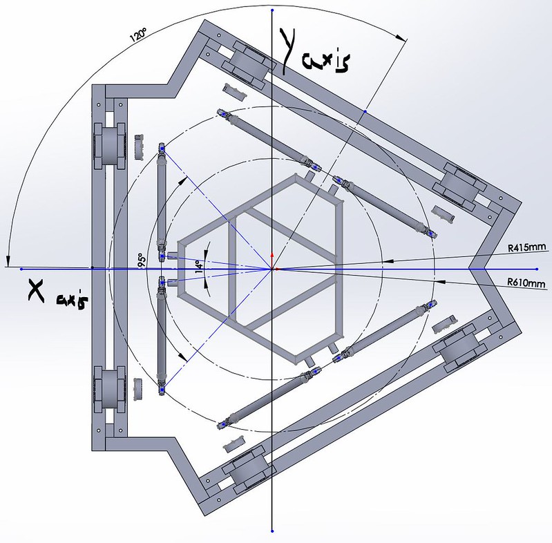 Using the stand alone program the "3D Simulation" image looks like this. 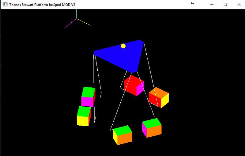 And all motion is correct when moving the sliders. When I click on Thanos6DOF within X-sim the "3D Simulation" looks like this 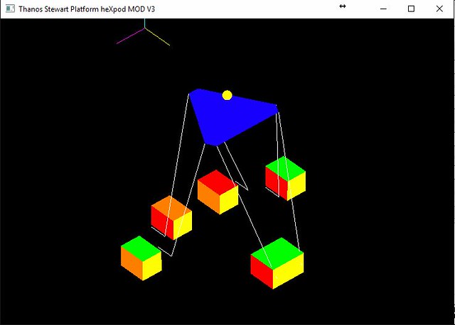 and all sliders are swapped...Surge=Sway Roll=Pitch...etc Here is the .ini file [6DOF_design] Base_Ratio=1.000000 Platform_Ratio=1.000000 Platform_Height=117.000000 Servo_Arm_length=16.000000 [6DOF_limiters] Max_displacement=80.000000 Crossing_Sensitivity=6.000000 Knee_Cap_limit=70 Servo_Rotate_Limit=130 [6DOF_input_limits] Yaw_Limit=10 Pitch_Limit=10 Roll_Limit=10 Surge_Limit=10 Sway_Limit=10 Heave_Limit=10 [6DOF_Center_of_Gravity] X=0.000000 Y=0.000000 Z=20.000000 [Settings] SW_Simulation=0 Invert_Servo_Values=0 [6DOF_heaveOffset_surgeOffset] Heave=0.000000 Surge=0.000000 [Servo_Orientation] Servo5=0.000000 Servo6=0.000000 Servo1=0.000000 Servo2=0.000000 Servo3=0.000000 Servo4=0.000000 [Coordinates] Base_1X=-41.200000 Base_1Y=-45.100000 Base_1Z=-150.000000 Base_2X=-41.200000 Base_2Y=45.100000 Base_2Z=-150.000000 Base_3X=-18.200000 Base_3Y=58.100000 Base_3Z=-150.000000 Base_4X=59.500000 Base_4Y=13.300000 Base_4Z=-150.000000 Base_5X=59.500000 Base_5Y=-13.300000 Base_5Z=-150.000000 Base_6X=-18.200000 Base_6Y=-58.100000 Base_6Z=-150.000000 Platform_1X=-41.200000 Platform_1Y=-5.000000 Platform_1Z=0.000000 Platform_2X=-41.200000 Platform_2Y=5.000000 Platform_2Z=0.000000 Platform_3X=16.200000 Platform_3Y=38.200000 Platform_3Z=0.000000 Platform_4X=25.000000 Platform_4Y=33.200000 Platform_4Z=0.000000 Platform_5X=25.000000 Platform_5Y=-33.200000 Platform_5Z=0.000000 Platform_6X=16.200000 Platform_6Y=-38.200000 Platform_6Z=0.000000 I know the height is off and I will work on that next. Thanks for all your help. Kind Regards, GA Dawg |
|
|
|
Post by hexpod on May 27, 2016 16:38:36 GMT
When you look at the datasheet for the resolution : 0,088 ° for the 360 ° travel and 0,011° for the 45 ° travel , i suppose that the resolution is not the same between the models 360° and 180° link to the datasheet please
cheers
|
|
|
|
Post by hexpod on May 27, 2016 16:42:40 GMT
Hi HeXpod, I did some more testing. And this is definitely how the X and Y when doing the measurement in CAD (in my case SolidWorks). Using the stand alone program the "3D Simulation" image looks like this. And all motion is correct when moving the sliders. When I click on Thanos6DOF within X-sim the "3D Simulation" looks like this and all sliders are swapped...Surge=Sway Roll=Pitch...etc Here is the .ini file [6DOF_design] Base_Ratio=1.000000 Platform_Ratio=1.000000 Platform_Height=117.000000 Servo_Arm_length=16.000000 [6DOF_limiters] Max_displacement=80.000000 Crossing_Sensitivity=6.000000 Knee_Cap_limit=70 Servo_Rotate_Limit=130 [6DOF_input_limits] Yaw_Limit=10 Pitch_Limit=10 Roll_Limit=10 Surge_Limit=10 Sway_Limit=10 Heave_Limit=10 [6DOF_Center_of_Gravity] X=0.000000 Y=0.000000 Z=20.000000 [Settings] SW_Simulation=0 Invert_Servo_Values=0 [6DOF_heaveOffset_surgeOffset] Heave=0.000000 Surge=0.000000 [Servo_Orientation] Servo5=0.000000 Servo6=0.000000 Servo1=0.000000 Servo2=0.000000 Servo3=0.000000 Servo4=0.000000 [Coordinates] Base_1X=-41.200000 Base_1Y=-45.100000 Base_1Z=-150.000000 Base_2X=-41.200000 Base_2Y=45.100000 Base_2Z=-150.000000 Base_3X=-18.200000 Base_3Y=58.100000 Base_3Z=-150.000000 Base_4X=59.500000 Base_4Y=13.300000 Base_4Z=-150.000000 Base_5X=59.500000 Base_5Y=-13.300000 Base_5Z=-150.000000 Base_6X=-18.200000 Base_6Y=-58.100000 Base_6Z=-150.000000 Platform_1X=-41.200000 Platform_1Y=-5.000000 Platform_1Z=0.000000 Platform_2X=-41.200000 Platform_2Y=5.000000 Platform_2Z=0.000000 Platform_3X=16.200000 Platform_3Y=38.200000 Platform_3Z=0.000000 Platform_4X=25.000000 Platform_4Y=33.200000 Platform_4Z=0.000000 Platform_5X=25.000000 Platform_5Y=-33.200000 Platform_5Z=0.000000 Platform_6X=16.200000 Platform_6Y=-38.200000 Platform_6Z=0.000000 I know the height is off and I will work on that next. Thanks for all your help. Kind Regards, GA Dawg Tell me why the instructions are not clear to you. I wrote several times to swap x with y in the .ini
try this:
[6DOF_design]
Base_Ratio=1.000000
Platform_Ratio=1.000000
Platform_Height=50.000000
Servo_Arm_length=16.000000
[6DOF_limiters]
Max_displacement=80.000000
Crossing_Sensitivity=25.000000
Knee_Cap_limit=90
Servo_Rotate_Limit=90
[6DOF_input_limits]
Yaw_Limit=25
Pitch_Limit=30
Roll_Limit=30
Surge_Limit=25
Sway_Limit=25
Heave_Limit=20
[6DOF_Center_of_Gravity]
X=0.000000
Y=-8.000000
Z=20.000000
[6DOF_heaveOffset_surgeOffset]
Heave=-11.000000
Surge=0.000000
[Servo_Orientation]
Servo5=-2.094395
Servo6=1.047198
Servo1=0.000000
Servo2=3.140000
Servo3=2.094395
Servo4=5.235988
[Coordinates]
Base_1X=-45.100000
Base_1Y=-41.200000
Base_1Z=-150.000000
Base_2X=45.100000
Base_2Y=-41.200000
Base_2Z=-150.000000
Base_3X=58.100000
Base_3Y=-18.200000
Base_3Z=-150.000000
Base_4X=13.200000
Base_4Y=59.500000
Base_4Z=-150.000000
Base_5X=-13.300000
Base_5Y=59.500000
Base_5Z=-150.000000
Base_6X=-58.100000
Base_6Y=-18.200000
Base_6Z=-150.000000
Platform_1X=-5.000000
Platform_1Y=-41.200000
Platform_1Z=0.000000
Platform_2X=5.000000
Platform_2Y=-41.200000
Platform_2Z=0.000000
Platform_3X=38.200000
Platform_3Y=16.200000
Platform_3Z=0.000000
Platform_4X=33.200000
Platform_4Y=25.000000
Platform_4Z=0.000000
Platform_5X=-33.200000
Platform_5Y=25.000000
Platform_5Z=0.000000
Platform_6X=-38.200000
Platform_6Y=16.200000
Platform_6Z=0.000000
|
|
|
|
Post by vicpopo on May 27, 2016 17:46:00 GMT
|
|
|
|
Post by hexpod on May 27, 2016 22:28:11 GMT
with the same ini content the dll and exe versions should definitely display the same geometry
@ga-Dawg did you read this instruction?
"- In the .exe version, after modifying the base/platform coordinates and after loading them from the .ini file, you have to click on the "platform/base size" sliders to update the changes in the 3d representation."
Keep us posted if the MOD works with your rig...
cheers |
|
|
|
Post by GA-Dawg on May 28, 2016 9:49:51 GMT
Hi HeXpod, I apologize if I seam to not be reading what your posting. I suffer from dyslexia and reading is difficult for me. It is also why I use a number of images as it easier for me to grasp the concepts. So I thank you for your patience I am really trying to understand and contribute in anyway I can. The .ini file you posted did in fact produce the motion in the desired directions. I than went back to SolidWorks and using those corrected positions I recalculated that layout that would illustrate this.  I know my height is off and I will go back and re-read the thread to hopefully be able to understand how I need account for this. One thing I did notice is the height doesn't seam to impact the Z axis in the coordinates. Does this matter. Cheers, GA Dawg |
|


