|
|
Post by vicpopo on May 16, 2016 16:14:34 GMT
Hi hexpod,
First thanks to improve the plugin.
I tested the .exe you posted on the 13 May.
I setup all the value coresponding to my 6dof on your plugin.
First good news is that the angular value pitch, roll, yaw that the plugin calculates are the same as the real life .I compared these values with my plateform ( with another values filled in the 6dof plugin running with xsim !!).
For the surge sway and heave I'm not sure , I suppose that the values are in cm .For the heave 8 means 8cm vertical displacement ? Isn't it ?
Another notices:
- when running test program maybe change also the order surge and sway ( it's detail )
- when closing the plugin and re-launching the arm value filled was 16 , and not 11 as my setup.After pushing on read ini button it was good.That means that I have to,make after always read ini launching the plugin ?
After that I tried,to,play with the xsim plugin ( the old one) and I faced to some strange phenomenon.I used the button optimise which freeze the plugin a few seconds .And what was strange is'that my arms weren't being full horizontal as my originally setup !! But when clicking on the button connect to,xsim , everything went back to the horizontal position and in the plugin servo arm position are set to 0°.
Something I not yet fully understood.
Cheers
edit : as I test your plugin in .exe application on my laptop and not directly to my pc running with xsim ,I was wanting to plug the amc to,my laptop.
but unfortunatly the amc wasn't recognize by the application
|
|
|
|
Post by hexpod on May 16, 2016 20:20:14 GMT
"I setup all the value coresponding to my 6dof on your plugin."
After that, if your platform is still not moving exactly like in the 3d model, that can be because of different motor spacing and different orientation.
The default motor spacing is 120 deg. for all 6 motors and for the moment can not be changed in the GUI. The default motor orientation is +30deg./-30deg. in relation to the circle radius for each pair. That's the nature of the most common "In Line" design in our forum.
Providing to the user the flexibility to choose different spacing and different orientation should be considered as a priority in the future development of this plugin.
"I'm not sure , I suppose that the values are in cm"
All values without ° degree sign, should be considered as centimeters except platform/base size, which should be considered in meters.
"- when running test program maybe change also the order surge and sway"
Are you sure? Please test the last version from the post above.
"- when closing the plugin and re-launching the arm value filled was 16 , and not 11 as my setup."
That is the known bug which is present only in the .exe version. As the .dll plugin is functioning well, it's not a priority to correct this for the moment. I've noticed that .dll version is saving and reading automatically all changed values.
"what was strange is that my arms weren't being full horizontal as my originally setup !!"
After pressing optimize, an algorithm is calculating the best starting position for your platform. a small offset applied is needed for the better motion range. Each time you modify the geometry you should press it and keep those values.
After that, if your have a non symmetric pitch range, you can correct it by applying a small offset for the surge, in the "center of gravity" column.
P.s.
To get in an easy way your platform height, you can measure your leg length from joint to joint, than in the GUI press the "show" button, and move the "platform height" cursor until the "leg length" value fits your measurement.
Hope it helps,
cheers.
|
|
|
|
Post by vicpopo on May 16, 2016 20:57:05 GMT
Ok Thanks hexapod .
For the ps that exactly what I've done ;-)
When spending some time to play with the .exe I noticed the correlation between changing height value and arm length !
For the optimize button and its feature I understand but something disturbs me . The problem is the center of the angle sensor range.As I have sensors with 180 angle course , if the optimize feature choose an another starting position , I would have to change the sensor angle position in order that the center of the sensor range match again at this new postion.If not some arms postion should overshooted .
One solution would be to,have sensors with more than 180 ° range measurements .It would secure that the sensor range is always ok.
|
|
|
|
Post by hexpod on May 16, 2016 21:39:21 GMT
Ok Thanks hexapod . For the ps that exactly what I've done ;-) When spending some time to play with the .exe I noticed the correlation between changing height value and arm length ! For the optimize button and its feature I understand but something disturbs me . The problem is the center of the angle sensor range.As I have sensors with 180 angle course , if the optimize feature choose an another starting position , I would have to change the sensor angle position in order that the center of the sensor range match again at this new postion.If not some arms postion should overshooted . One solution would be to,have sensors with more than 180 ° range measurements .It would secure that the sensor range is always ok. "I noticed the correlation between changing height value and arm length !"
I suppose you mean leg length :-)
"something disturbs me . The problem is the center of the angle sensor range."
Good point!
The simplest solution would be just to put the "servo limit" below 90 deg.
Otherwise, if you use pulleys for the sensing, you could change them for a slightly bigger size. Also you could go with 270deg sensors.
"if the optimize feature choose an another starting position , I would have to change the sensor angle position in order that the center of the sensor range match again at this new position."
I don't feel the logic here.
The question is, if we put the same heave offset mechanically (with sensors) and leave the software with the arms at 0 deg. would we get the same geometrical result as by doing the opposite? (mechanics at 0 deg. and plugin offset correction)
cheers
|
|
|
|
Post by vicpopo on May 17, 2016 5:30:16 GMT
Hi hexapod , Yes leg lenght , I thought right but wrote wrong ! For the point you said you don't feel the logic , it's the problem for the sensor range .I will make a litlle drawing to explain. @thanos : you consider in the amc soft a full range sensor.If there is a gear ratio for the sensor between the gear box axle and the sensor axle , how you can consider it ? edit : drawing 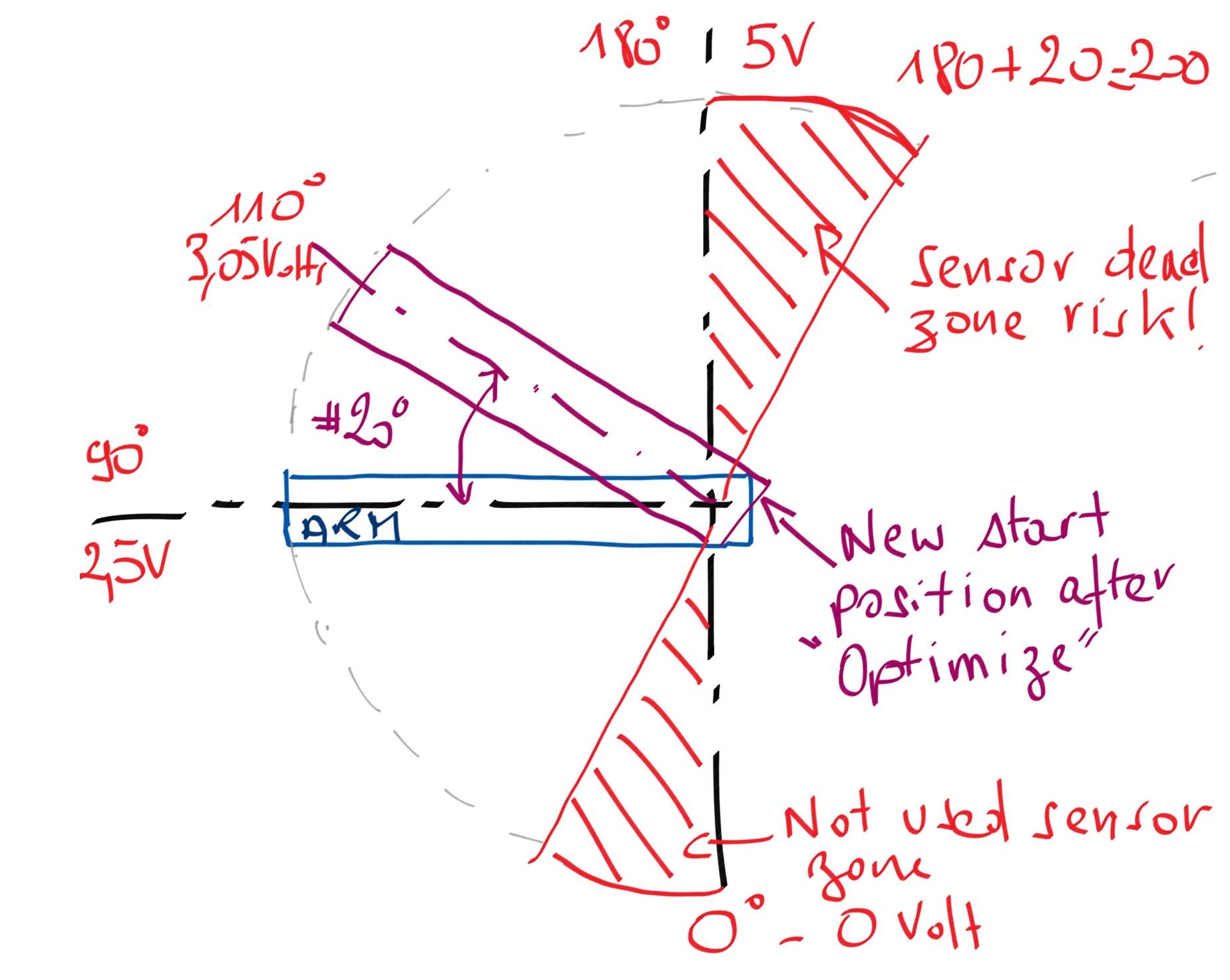 If my originally setup for the sensor position is at 90° matches to 2,5 volts ( that I made because I can easily turn my sensor to setup,this position).That means for my sensor the arm full up is 180° and full down is 0°. After optimize with the plugin the new zero position is 20° arm up , so 110° ( 3,05 volts) without new mechanical sensor setup .In this case I have the risk that the positions up,to 180° are now in the dead sensor zone. What surprise me alos a little bit because after optimize I watched servo position from 20° to 39° for new starting position.I feel theses values very big considering the fact that when the arm goes up ( considering thes new starting position ) , you are in a arm travel where angular displacement are big for very short vertical displacement and the same result for the linear speed (z linear speed particulary ) I agree that the starting position full horizontal is not the best value but I'm a little bit surprised by these values after optimize calculation. Logically considering these new values and with the fact that my sensor range is 180° , I must note these values for each motor and after try to setup mechanicaly the starting position with them .In order with my drawing as example, that the arm setup at 110° must have the sensor voltage at 2,5 volts and not 3,05 volts. Oh I forgot one more time to thank you for finding the reason what disturb the communication for the amc ( the kill switch button). As I said I test your changes for the plugin with my laptop.And xsim won't recognize the amc , I remember the tip for the kill switch and after the amc would well recognised. |
|
|
|
Post by vicpopo on May 17, 2016 8:27:51 GMT
Edit : so tested a little bit .
Forgotten to mention from the post above is the center of the gravity position .I 've got start position with high value ( more than 30°) having the values sway=0 ,surge=2,heave =0.
These values have a big influence for the starting position and in particulary heave position.
I tested with sway=0 ,surge=2,heave =15 and I haven't any starting position up to 20°. That is a good deal.
Now the only part missing is a flat surge .The sway is quiet flat but not yet the surge !!
But any way a big progress ...
What is the feature invert servo position check box in the plugin ?
|
|
|
|
Post by hexpod on May 17, 2016 10:36:32 GMT
Edit : so tested a little bit . Forgotten to mention from the post above is the center of the gravity position .I 've got start position with high value ( more than 30°) having the values sway=0 ,surge=2,heave =0. These values have a big influence for the starting position and in particulary heave position. I tested with sway=0 ,surge=2,heave =15 and I haven't any starting position up to 20°. That is a good deal. Now the only part missing is a flat surge .The sway is quiet flat but not yet the surge !! But any way a big progress ... What is the feature invert servo position check box in the plugin ? Interesting point! You mean, that the "center of gravity" values have also an influence on "optimize" offset calculations.
"starting position up to 20°. That is a good deal."
You could maybe test my previous idea and see if it helps.
Revert the software heave offset to 0. (servo arm angle - 0 deg.) Put now the pervious software heave offset using sensors (2.5V 20 deg. up)
However I think that the correct way to proceed is with sensor 2.5V set horizontally and software heave offset.
In the following example with 180deg sensor you could get 143.5 deg. working range and with 270 deg. sensor 188.5 deg. working range. 
|
|
|
|
Post by vicpopo on May 17, 2016 10:40:05 GMT
Edit : test on my 6dof in real life.
First it works perfectly , thanks for your great job heXapod !
And I would say that I have the best motion when using the optimise feature .I tested with servo at 0° coresponding on my 6dof at the arm full horizontal and the feeling is not so good after the optimisation.
Cheers
edit : and yes the center of gravity points surge, sway , heave have a big influence for calculating the arm angle offset.Thanks for your advice to adjust the sensor.I looked at the specs , there is a full turn sensor 360 but not sure for a 270° angle travel.Will again have a look.
|
|
|
|
Post by hexpod on May 17, 2016 10:54:25 GMT
"But any way a big progress ..."
Please report if you think the new .dll file can advantageously replace the old plugin in the x-sim package.
|
|
|
|
Post by vicpopo on May 17, 2016 11:01:01 GMT
You want that I contact Sirnoname to inform him what you made for the plugin ?
|
|
|
|
Post by hexpod on May 17, 2016 11:04:54 GMT
You want that I contact Sirnoname to inform him what you made for the plugin ? we should maybe have another feedback from another tester before uploading...
Anyone interested??
|
|
|
|
Post by vicpopo on May 17, 2016 17:26:26 GMT
I made some tests with pcars on the Nordschleife with 2 marvolus cars and I confirm that your modified plugin works great.
You can propose your plugin as it is now and people can test. They put the old files into a folder and test the new one. That's it ;-)
And question of the motion feeling no doubt that is better !
Cheers and big thanks to you !
|
|
|
|
Post by tronicgr on May 17, 2016 20:19:58 GMT
Well done Ignacy!
Thanks for all your efforts. I'll try to add the buttons as requested as soon I find some time.
I'll try it on my model platform to verify the motion of the modified plugin in regards the dimensions.
Can you remind me the things to be fixed on the amc1280usb firmware? I'll be coding a few functions on the firmware so I might as well fix those too now.
Thanks
Thanos
|
|
|
|
Post by tronicgr on May 17, 2016 20:27:44 GMT
Hi hexapod , Yes leg lenght , I thought right but wrote wrong ! For the point you said you don't feel the logic , it's the problem for the sensor range .I will make a litlle drawing to explain. @thanos : you consider in the amc soft a full range sensor.If there is a gear ratio for the sensor between the gear box axle and the sensor axle , how you can consider it ? edit : drawing If my originally setup for the sensor position is at 90° matches to 2,5 volts ( that I made because I can easily turn my sensor to setup,this position).That means for my sensor the arm full up is 180° and full down is 0°. After optimize with the plugin the new zero position is 20° arm up , so 110° ( 3,05 volts) without new mechanical sensor setup .In this case I have the risk that the positions up,to 180° are now in the dead sensor zone. What surprise me alos a little bit because after optimize I watched servo position from 20° to 39° for new starting position.I feel theses values very big considering the fact that when the arm goes up ( considering thes new starting position ) , you are in a arm travel where angular displacement are big for very short vertical displacement and the same result for the linear speed (z linear speed particulary ) I agree that the starting position full horizontal is not the best value but I'm a little bit surprised by these values after optimize calculation. Logically considering these new values and with the fact that my sensor range is 180° , I must note these values for each motor and after try to setup mechanicaly the starting position with them .In order with my drawing as example, that the arm setup at 110° must have the sensor voltage at 2,5 volts and not 3,05 volts. Oh I forgot one more time to thank you for finding the reason what disturb the communication for the amc ( the kill switch button). As I said I test your changes for the plugin with my laptop.And xsim won't recognize the amc , I remember the tip for the kill switch and after the amc would well recognised. The amc1280usb cannot know the physical travel capabilities of a sensor. Either it's 180 degrees or 360 degrees it will always just read the 0-5v of the output of the sensor and try to position the motor according to the reading. What you can do is to calculate the sensor travel in the software taking in consideration the sensor limits that by default is 10% (5% each direction) to avoid overshoot of the target and have unwanted 360 degrees rotation of the motor. Thanks Thanos |
|
|
|
Post by hexpod on May 18, 2016 13:47:20 GMT
changelog from initial heXpod MOD version:
- added buttons for swapping the servo orientation
- servo orientation. additional custom orientation values can be saved/read in/from the .ini file
experimental:
additional custom "servo center"/"upper joints" coordinates values can be saved/read in/from the .ini file
This should give the possibility to fit and drive perfectly every existing design.
By editing the .ini file you can fit and design without any restrictions a creative model of your choice.
Notice:
While modifying the base/platform coordinates, after reading from .ini file you have to click on the platform/base size sliders to update the changes in the 3d model.
To reset to original position, press in order "reset position" - save .ini" "- read.ini" than move the base/platform sliders.
cheers
|
|


