|
|
Post by GA-Dawg on Apr 19, 2016 17:59:12 GMT
I am ready to start test but need a little help. I know that I have to set the AMC to 135 pos and 246 neg but do I also need to filp the 24v wires as well? 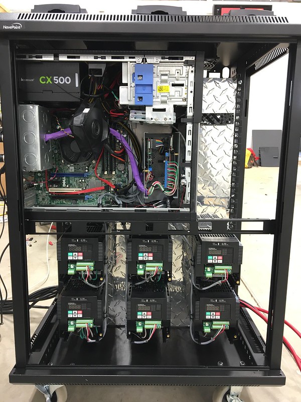 |
|
|
|
Post by paulg100 on Apr 19, 2016 19:08:14 GMT
you can leave the 135 pos 246 neg.
then just switch the 24v a/b outputs until you get the correct behavior which is the arm should rotate until it reaches home (measured by the pot) then stop.
then when you press left/right on amc should rotate then when you let go, should return to home.
If the arm rotates then stops and starts oscilating hard or just turns the wrong way then you need to switch the a/b (or 1/2)
can either do this at the amc end A/B or switch the 1/2 wires at the vfd end.
oddly enough ive ended with all motors apart from no4 set to 1-b 2a. dont ask me why but was easier to just switch wires around until i got the correct behavious visually rather than try to make it match 135 246.
|
|
|
|
Post by GA-Dawg on Apr 23, 2016 15:50:07 GMT
Success... I had to go back to the starting board. The motors that I have will not autotune with the Hitachi autotune feature when they are wire for delta so I am back to star wiring and everything is going much better. | F002 | Acceleration time (1)
|
| Set value
| .15 | (this is the lowest I could get without getting a error) | | F003 | Deceleration time (1) |
| Set value | .15 |
| | A001 | Frequency source
|
| Set value
| 01 | (Control Terminal) | | A002 | Run command source |
| Set value
| 01 | (Control Terminal)
| | A044 | V/f characteristic curve |
| Set value
| 03 | (Sensorless vector) | | A051 | DC braking enable |
| Set value
| 01 | (enable during stopping) | | A054 | DC braking force for deceleration |
| Set value
| 80 | (default is 50 I increased it to 80) | | A082 | AVR voltage select |
| Set value
| 03 | (230) this should match the name plate on the motor | | b083 | Carrier frequency |
| Set value
| 15 | (increased to control noise) | | H002 | Motor constant selection |
| Set value
| 02 | (Auto tuned data) |
I will have to update the build log to reflect the change. flic.kr/p/G73Pmo |
|
|
|
Post by bimmer635csi on Apr 24, 2016 3:06:30 GMT
Its been a while since I commented here, but things are looking good for you GA-Dawg. Nice work. I modified your design slightly and made an animation of how I intend to go forward (assuming I get suitable living arrangements for such things). Good thing I have a required delay in construction though, because it allows me to tweak the design to minimize material and assembly time. The video is here on U2B: youtu.be/BCefl2we-DAThanks for the initial idea of layout. Cheers, Chris |
|
|
|
Post by GA-Dawg on Apr 25, 2016 13:56:28 GMT
Hey Chris,
Very Cool...I noticed that you have the arch on the outside vs inside. I've not seen that done before and I read that it was not recommended (don't remember why). Also start thinking about your wiring. It will save you time later.
Cheers,
Brian
|
|
|
|
Post by GA-Dawg on Apr 25, 2016 13:57:52 GMT
First run
|
|
|
|
Post by GA-Dawg on Apr 25, 2016 14:32:17 GMT
(This post is not yet complete...last updated June 23 2016) Tuning
NOTE: DO THIS WITH THE TOP PLATFORM OFF.
First we need to tune the Hitachi. To do this you will need to set some basic parameters. This can be done by the front panel or the Hitachi software. A044
| V/f characteristic curve
| Set value
| 03 | (Sensorless vector)
| A082
| AVR voltage select
| Set value
| 03 | (230) this should match the name plate on the motor
| b083
| Carrier frequency
| Set value
| 15 | (increased to control noise)
| H002
| Motor constant selection
| Set value
| 02 | (Auto tuned data)
|
Now we need to find the lowest Acceleration/Deceleration time that will work without generating an error. So change the following F002
| Acceleration time (1)
| Set value
| .05 | | F003 | Deceleration time (1)
| Set value
| .02 | | H001 | Auto-tuning selection
| Set value | 02 |
With H001 set, run the motor...it will go through the autotune function. Note: H001 will go to disabled after you start the motor. If it errors out (EXXXXXX on the Hitachi display) you will need to do it again with a higher F002. Do this on all motors and recorded the F002/F003 settings. Once complete set all the motors with the highest F002/F003 numbers found. Example...Motor 2 autotunes at F002 of .09, Motor 4 autotunes at .20. Motor 4 has the highest F002 number of all the motors. Set all motors F002 to .20 As a reference I ended up with | F002 | Acceleration time (1)
| Set value | .20 | | F003 | Deceleration time (1)
| Set value | .02 |
Now that all the motors are correctly tuned we add in the break controller and AMC1280USB control | A001 | Frequency source | Set value | 01 | Control Terminal | | A002 | Run command source | Set value | 01 | Control Terminal | | B090 | Dynamic braking usage ratio | Set value | 10 |
| | B095 | Dynamic braking control (BRD) selection | Set value | 02 | (Enable always) | | B130 | Deceleration overvoltage suppression enable | Set value | 01 | (Enabled) | A051
| DC braking enable
| Set value | 01 | (enable during stopping) | A054
| DC braking force for deceleration
| Set value | 80 | (default is 50 I increased it to 80 but it's something that you can experiment with) |
One thing to note. You really want the Accl/Decl as low a possibly. After I had everything working with BFF I went back in a reduced the Accl/Decl. In the end I ended up with these values. | F002 | Acceleration time (1)
| Set value
| .18
| | F003 | Deceleration time (1) | Set value
| .02
|
Now its time to power up AMC1280USB by plugging it to USB port, the motors will move the levers to "home" but some will oscillate because of configuration of the motors. Rotate the AMC shaft until you find the sensor direction and change it to Neg 135, Pos 246. Now all the motors should be at "home" and not be oscillating. 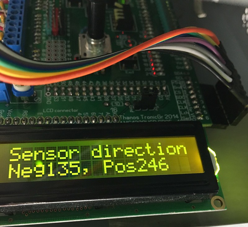 "Home" is the mid stroke of the lever arm. Move the position sensor until the lever arms is at mid stroke (see image). If you built the machine per the blueprints that means home is 41.47 degrees from the horizontal plane 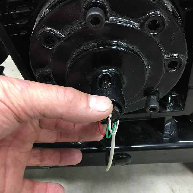 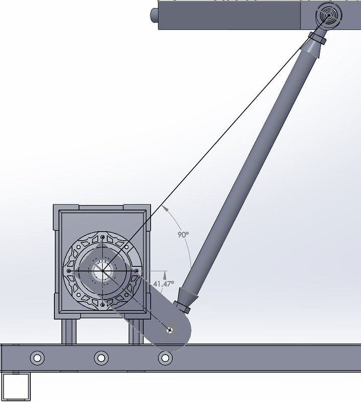 once they are all set to "home" it's time to run Fabi's software to set the AMC1280USB |
|
|
|
Post by bimmer635csi on Apr 26, 2016 0:48:03 GMT
Hey Chris, Very Cool...I noticed that you have the arch on the outside vs inside. I've not seen that done before and I read that it was not recommended (don't remember why). Also start thinking about your wiring. It will save you time later. Cheers, Brian Brian, I have already started laying out wiring paths since I'm still only in the planning stage. I can't quite decide if it will be worth routing through the frame or not and with my current design the wiring box on the side of the motors are not on the same side of the platform, so the wiring might be a mess unless I can find a motor with a changeable base plate or wiring inlet. I just noticed compared to your video that my control arms on the gearboxes are backwards compared to yours. I'm guessing that's the arch you refer to. I'll change it up and see what I can do. Is the idea to have the push rods as close together as possible or is it just that the platform moves more with the actuation toward the center? After reviewing the SketchUp model, I think I've found a way to make the platform smaller still without relocating the motors / gearboxes, but if the idea is to get the gearboxes as close together as possible, the size can be reduced significantly further. Your video looks great. Congrats on the progression. Cheers, Chris |
|
|
|
Post by GA-Dawg on Apr 26, 2016 1:41:06 GMT
Things are going great after setting A013 to 2. I do have a question. I have been working on setting P with Fabi's configurator software and haven gotten up to 40 and still have not seen the osculation. Does that sound right and high is to high for a P value.
|
|
|
|
Post by GA-Dawg on Apr 26, 2016 1:54:13 GMT
Chris,
Yes the idea is to have the rods push up from the center. If you change the distances you will need to figured out the angles so you can plug them into the sim software. Let me know if that does not make sense.
-GA Dawg
|
|
|
|
Post by paulg100 on Apr 26, 2016 5:55:05 GMT
"I do have a question. I have been working on setting P with Fabi's configurator software and haven gotten up to 40 and still have not seen the osculation. Does that sound right "
Yes I think so, somewhere in fabi's blog he listed his final PID after lots of tuning. If I remember correctly his P was really high. over 100 I think?. It just depends on the I and D values.
On a side note, seeing your platform running at 80% gave me an idea, I increased my online motor speed from 15% which I was using for testing to 40%. It actually made my platform
run much better, so it looks like having the speed set to low can cause as many issues as to high.
|
|
|
|
Post by GA-Dawg on Apr 26, 2016 11:21:53 GMT
Paul,
That's great news. I also want to thank you for posting your setup. As you know a few of us have adopted the computer 1/2 rack and cap ideas. Once I get back I will finish up this build log, it's been a great project and I am really looking forward to spending time in the seat.
Cheers,
-GA Dawg
|
|
|
|
Post by Trip Rodriguez on May 5, 2016 10:22:14 GMT
Thank you for making this guide! I'm working on a very similar platform and it is a big help to have everything in one place!
I bought the same motors and gearboxes as Stevant, I'm pretty sure they are identical motors to yours but my gearboxes are different and I think 50:1 ratio.
I'm kinda glad this wasn't up when I started or the price would have discouraged me, fortunately I'm already committed having bought the motors, gearboxes, inverters, Thanos boards, and tie rods, as well as had custom crank arms so I'm committed! =D.
I was inactive for a long time but I'm hoping to be back to working on this project as soon as I complete another one that I hope will be done in about a week and a half!
Again, thanks for the guide. This should be easier than hunting through various different build threads looking for this info.
Trip
|
|
|
|
Post by billo2404 on May 7, 2016 1:27:00 GMT
bellissima realizzazione e grande cura dei dettagli, bravo!!!
Posso chiederti quale miglioramento portano i condensatori sui segnali 24V?
beautiful construction and great attention to detail, bravo !!!
Can I ask what improvements bring the capacitors on the 24V signals?
|
|
|
|
Post by paulg100 on May 7, 2016 7:38:47 GMT
"Can I ask what improvements bring the capacitors on the 24V signals?"
Hi Billo,
It acts as a signal conditioner and helps reduce noise in the loop.
I had lots of emi issues initially and with thanos's help this worked out to be a good solution.
Most benefit is probably for longer signal cable runs like those to the pots.
|
|


